Eeg&emg Recording Manual
An official manual for synapse from Tucker-Davis Technologies (TDT). And also some video tutorials. We use the PZA SI-4 preamplifier and RZ10 LUX integrated processor hardware.
This manual contains some most frequently used functions for sleep EEG/EMG recording.
Recording setup
An official manual for synapse from Tucker-Davis Technologies (TDT). And also some video tutorials
Experiment and object setup
We highly recommend you to create a new experiment and object with your own, unless you have to record with others. Here is the official doc about managing user and subjects.
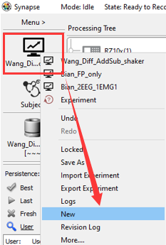
To create a new experiement, click the experiment area, and select New option.
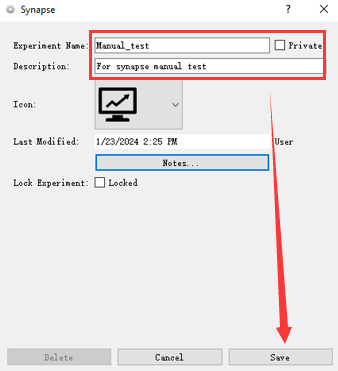
 Setup the name and description, then you created a new experiment.
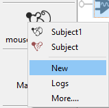
Same with experiment, you can set a subject.
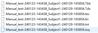
Note: The experiment and object you set will store as your save path name (See picture below), my experiment name is Manual_test and subject name is subject1, and in the file name, there are also time information of your recording.
Stream setup
You can setup your stream with or without referencer. Here we recommend to use the without referencer setup.
Note: referencer is a Gizmos of synapse. Check the official doc for Gizmos setup.
Without referencer
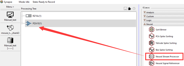
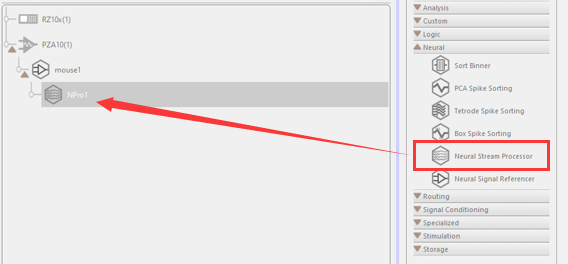
You can setup all channel you want to record in this setup. Firstly you need to drag some neural stream processor for the Neural category to the PZA10 area.
 Setup each processor for your recording. Here is an
 example of two EEG (frontal and parietal), two EMG (left and right neck muscle) and one Reference (cerebellum).
**Coming soon … **
With referencer
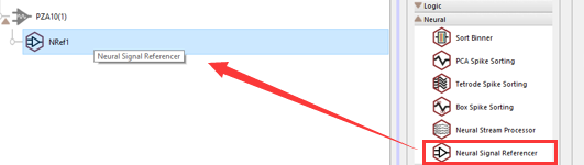
By using the referencer, need to grab a Neural Signal Referencer to the PZA10 first, which will be the reference of the Neural stream processors under it.
Here we use the example of one EEG (1st pin of the electrode), two EMG (left and right neck muscle, 3rd and 4th pins of the electrode) and one Reference (cerebellum, 2nd pin of the electrode). And the 4 pins connect to the bank in 1st~4th channels.
- Add a
Neural Signal Referencer.
- Setup the channel and some basic information of the referencer.
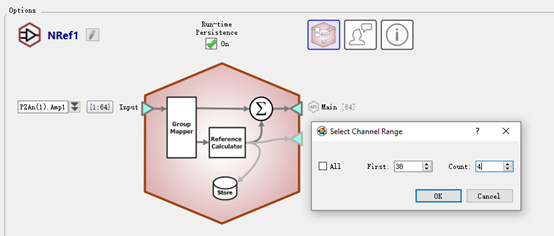
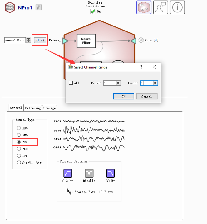
 In the
 Select Channel Range dialog, the First’s value should be your first channel of the bank. And the Count’s value should be the pin number of your electrode. Here in the example, First’s value should be 1 and count should be 4.
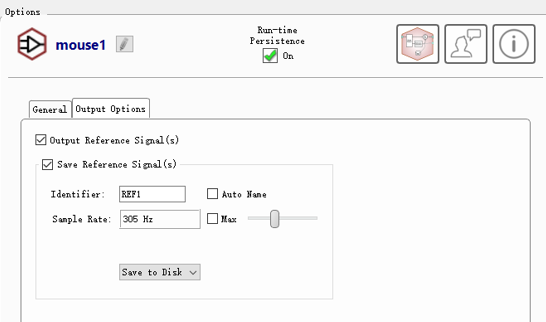
Don’t forget to check the Output Reference Signal(s) and Save Reference Signal(s), and set the proper values, unless you don’t want it.
- Add stream processor to the referencer and setup
Add a stream processor under the referencer.
Set up the channels of the stream processor, which the First and Count value is relative to the Referencer here. For the example, the First’s value here is 1 which means the EEG is the 1st pin of electrode, and Count’s value is 1 means we only got one EEG pin. Choose the type you want to use this stream for in the General -> Neural Type box.
Then you need to set the filter of the stream, which is in the Filtering area.
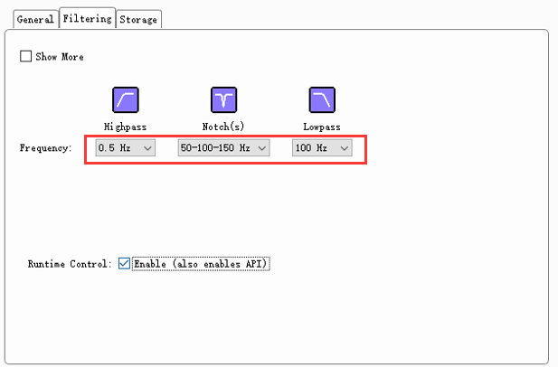
We recommend to set as follows (if you don’t have special experimental requirements):
- Highpass: 0.3 Hz for EEG recording and 10 Hz for EMG recording.
- Notch(s): 50-100-150 Hz to avoid current noise.
- Lowpass: 70 Hz or 100 Hz for EEG and 100 Hz for EMG.
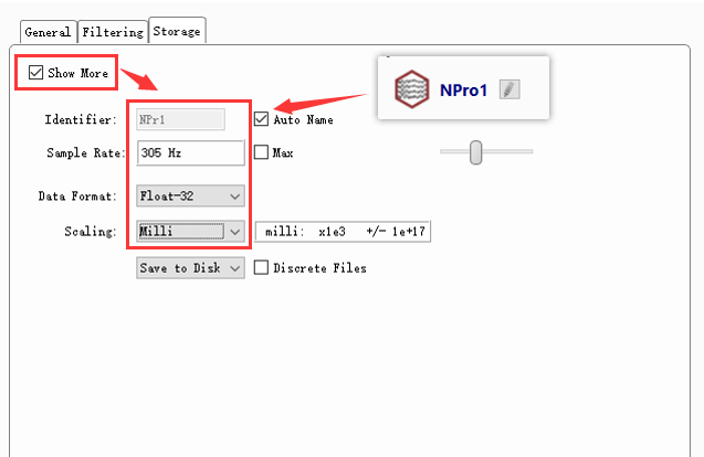
After that, it’s the final step, you need to identify the name of your stream processor, and the sample rate. The identifier name follows the stream processor’s name by default. The sample rate we recommend is 305 Hz,and the scaling we recommend is Milli.
EMG stream processor is almost the same. In this example, the channel of EMG setup is First: 3, Count: 2 which means the EMG is start from the 3rd pin and totally two.
Preview
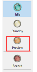
After all those settings, you can preview your signal in the Preview mode by clicking the Preview button.
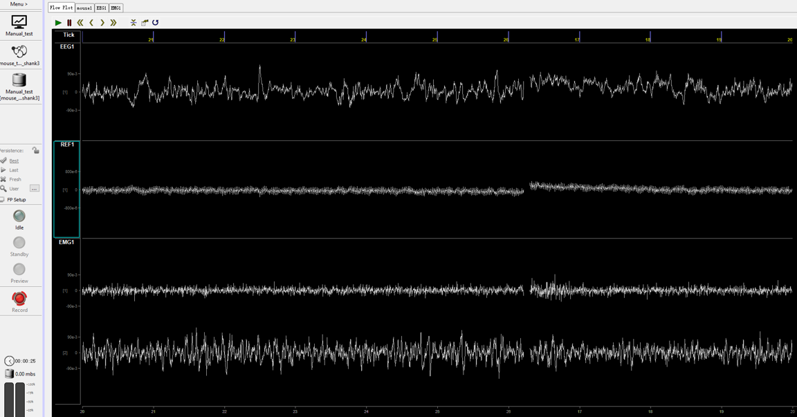
And you will see like the follow picture. Now it’s the original signal, with no reference set, and you can see the EEG and EMG have noise. You need to click the corresponding REF (Here is the ‘mouse1’ in the top bar), ans select one channel as your reference channel.
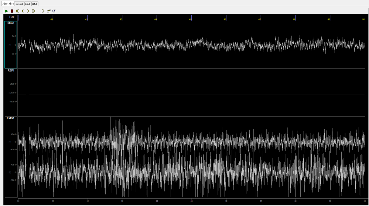
This is the original state of reference setting, it’s off.

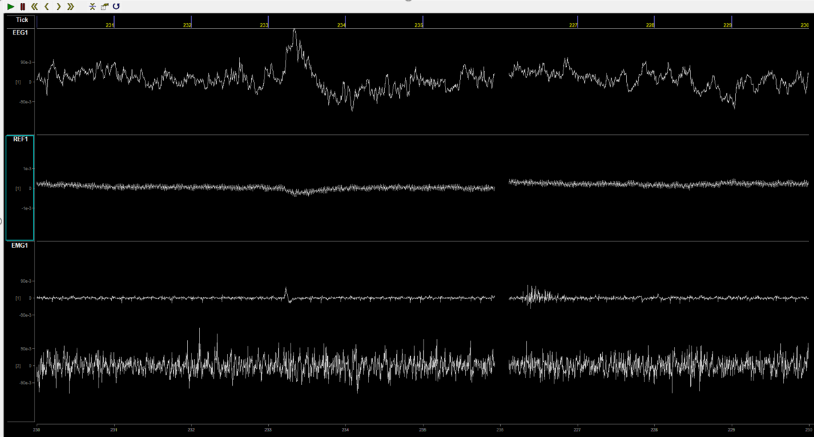
And you need to set it to your reference channel (the pin of your electrode seen as reference, here in the example is the 2nd pin).

After setting the reference, you will see the REF channel get signal input.
Note: if you use the without referencer mode, you have no need to set the reference channel, since the reference will record as a EEG signal.
Others
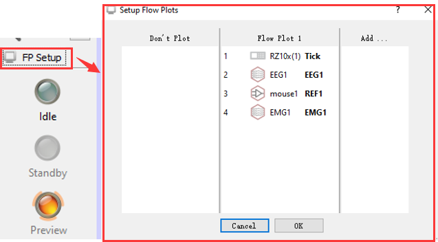
Flow plot
Here you can select channels to plot or not. And you can plot different mouse (subject) in different Flow plot, just by dragging the channel you want to the Add… column.
Note: No matter you plot the channel or not, and no matter which flow plot is your channel in, they will all be recorded in the record mode. Which means once you set the channel in the Idle mode, they will be recorded. So if there are any channel nobody wants, delete it from the Idle mode.
Tips
Some tips about preview mode and record mode.

The first button will auto adjust the scale of all channels, and the second button can help adjust the second of one page. Default is 10 second, you can set it to 30 seconds or 60 seconds.
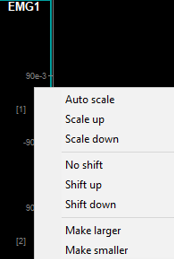
Hang your mouse on the channel, and press SHIFT with your mouse left button, with your mouse up/down, you can adjust the signal’s scale conveniently. And CTRL with the mouse left button, can shift the signal. Which will do the same thing with you right clicking the green area (See picture below)
Recording
After setup, you can start recording by click the red Record button. And you will see the same thing with what you saw in the preview mode.
Perfect signal!
Data saving
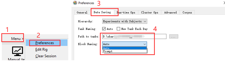
Menu -> Preferences -> Data Saving, You can set the data saving path, and Before each recording, especially auto start (See the auto start part), you need to ensure block Naming is Auto, unless you want to specify the name when the recording begin. (It will pop up an editor and the record won’t start unless you enter a block name.)
The data will be saved under the path you set in the Path to tanks. And the path is Experiment-date-time/Subject-date-time, the Experiment-date-time is the time you create the Experiment, and the Subject-date-time is the time started recording. (See picture below)
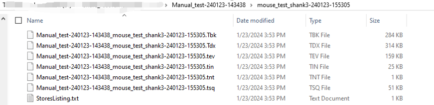
These are the original data file of TDT, and you can extract your data from them. (See Extract data section).
ZBusmon restart
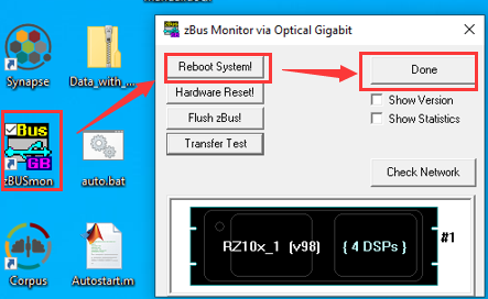
As TDT support said, it’s recommended to restart the ZBusmon before each recording (especially long time recording). The pathway is:
Close synapse -> Open ZBusmon on the desktop -> Reboot System -> Done
Auto start
You can also choose auto start.
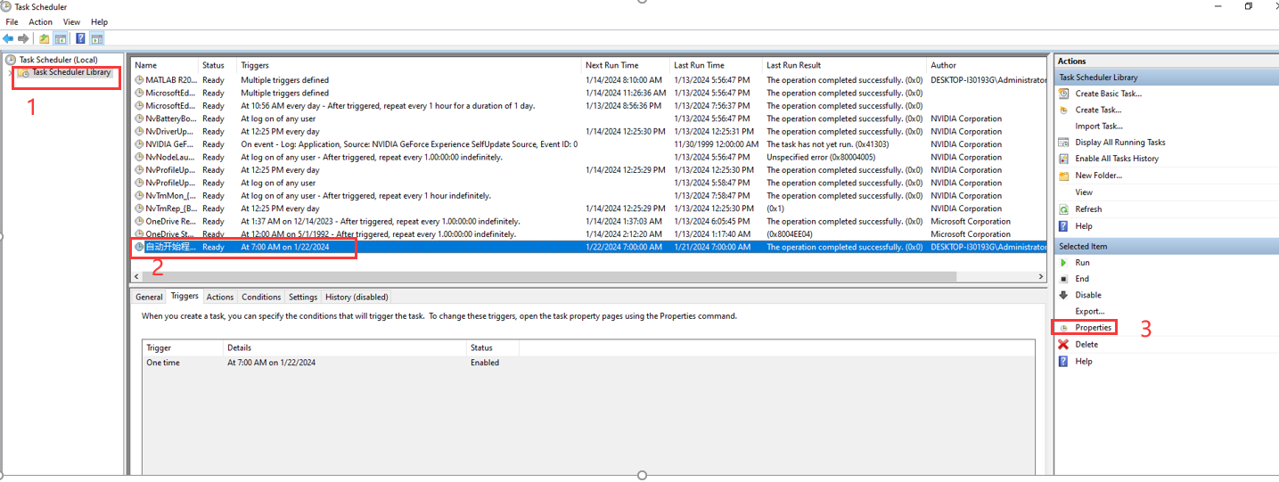
Auto start -> 自动开始程序 -> Properties -> Triggers,
Edit the time you want to start recording. Make sure the status is Enabled.
It will raise the auto.bat on the desktop (DO NOT CLICK IT MANUALLY), and run the Autostart.m script. You can set the parameters in the Autostart.m file.
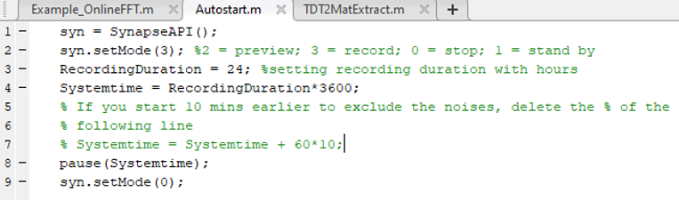
As the tdt recording system may have some noise at the start of recording, and starting the system takes about 30 seconds, here we recommend to start your recording 10 minutes earlier.
Extract data
For data extraction, see official doc of Offline Data Analysis Tools. Here a simple script for extraction to fit MiSleep:
SDKPATH = 'D:\TDTSDK'; % or whatever path you extracted the SDK zip into
addpath(genpath(SDKPATH));

tdt_data = TDTbin2mat('./Subject1-231109-182005');

data.EEG_F = tdt_data.streams.EEG1.data(1, :);
data.EEG_P = tdt_data.streams.EEG1.data(2, :);
data.EEG_DIFF = data.EEG_F - data.EEG_P
data.EMG_1 = tdt_data.streams.EMG1.data(1, :);
data.EMG_2 = tdt_data.streams.EMG1.data(2, :);
data.EMG_DIFF = data.EMG_1 - data.EMG_2;
data.REF = data.streams.mou1.data(1, :);
data.channels = {'EEG_F' 'EEG_P' 'EEG_DIFF' 'EMG_1' 'EMG_2' 'EMG_DIFF' 'REF'};
data.sf = {305.1758 305.1758 305.1758 305.1758 305.1758 305.1758 305.1758};
data.time = {'20240409-18:00:00'};
Data split
And for data split extraction, see the following codes of matlab:
% If you want to select a specific part of your raw data, which was
% extracted by the previous script, use the following codes
% Let's say your data was start recording from 09:29:56 AM to 13:30:04 PM,
% and you want to select the data from 10:30:00 AM to 13:30:00 PM
% This real start time is which you get from the StoresListing.txt

real_start_time = datetime(2024, 1, 28, 6, 50, 34);

% Set start time and end time of the part you want to select

select_start_time = datetime(2024, 1, 28, 7, 0, 0);
select_end_time = datetime(2024, 1, 29, 7, 0, 0);

% Get the seconds between real_start_time and select_start_time, and also
% between real_start_time and select_end_time

start_time_delay = seconds(select_start_time - real_start_time);
end_time_delay = seconds(select_end_time - real_start_time);

% Multiple the time delay with sampling rate, which is commonly 305 Hz, to
% locate the real data point in your real data to do selection

sampling_rate = 305;
select_start_data_point = start_time_delay * sampling_rate;
select_end_date_point = end_time_delay * sampling_rate;

% Use the data point location to select the data from raw data
% final_data(:, :) = raw_EEG_data(select_start_data_point: select_end_date_point, :);
% Change the 'raw_EEG_data' to your 'own raw data', which is 'EEGdata1' if
% you use the previous extraction script

final_data(:, :) = EEG_DATA_YOU_EXTRACTED(select_start_data_point: select_end_date_point, :);

% NOTE: this may raise error, you need to check the shape of your
% 'raw_EEG_data', if it's shape is '5x5099392' but not '5099392x5', you
% need to change the index position, which can be like this:

final_data(:, :) = EEG_DATA_YOU_EXTRACTED(:, select_start_data_point: select_end_date_point);

% If you had already got final data, don't run this again!